■ Rotaion correction
Since most smartphones are equipped with a gravity acceleration sensor and a geomagnetic (orientation) sensor, these can be used to calculate the three angles (Euler angles) that represent the orientation (posture) of the terminal. The following explains how to convert acceleration in a coordinate system fixed to the terminal to acceleration in a stationary coordinate system using the measured Euler angles.
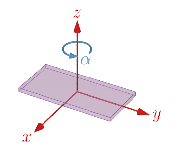
Rotation around the z axis
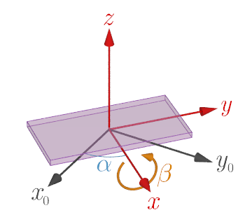
Rotation around the x axis
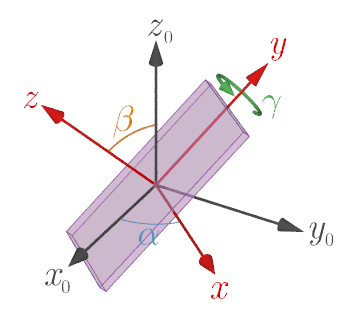
Rotation around the y axis
The acceleration measurement application on this site is a web application that runs in a web browser and is written in JavaScript. DeviceOrientationEvent and DeviceMotionEvent APIs are provided to detect device orientation information (Euler angle) and acceleration, respectively. The Euler angles α, β, and γ obtained by DeviceOrientationEvent represent the angles of rotation around the z, x, and y axes of the coordinate system fixed to the device in this order (z-x-y Euler angles). Note that these Euler angles are different from the roll-pitch-yaw angles (z-y-x Euler angles) commonly used in vehicles and robots.
Measuring the Euler angles from time to time, along with the acceleration measurements, gives an indication of how much the device has rotated relative to the stationary coordinate system at the start of the measurement. The rotation matrices Rz(α), Rx(β), Ry(γ) for the Euler angles α, β, γ are given by
$$ \tag{1} R_z(\alpha)=\begin{pmatrix} \cos\alpha & -\sin\alpha & 0 \\ \sin\alpha & \cos\alpha & 0 \\ 0 & 0 & 1 \end{pmatrix}, $$ $$ \tag{2} R_x(\beta)=\begin{pmatrix} 1 & 0 & 0 \\ 0 & \cos\beta & -\sin\beta \\ 0 & \sin\beta & \cos\beta \end{pmatrix}, $$ $$ \tag{3} R_y(\gamma)=\begin{pmatrix} \cos\gamma & 0 & \sin\gamma \\ 0 & 1 & 0 \\ -\sin\gamma & 0 & \cos\gamma \\ \end{pmatrix}. $$
Let us consider converting $\boldsymbol{a}_0=\left(a_{0x},\,a_{0y},\,a_{0z}\right)$ displayed in component representation in the stationary coordinate system to $\boldsymbol{a}=\left(a_{x},\,a_{y},\,a_{z}\right)$ in component representation in the coordinate system rotated by the z-x-y Euler angles. In this case, $\boldsymbol{a}$ is obtained by rotating $\boldsymbol{a}_0$ backward around the z axis by an angle α, then backward around the x axis by an angle β, and then backward around the y axis by an angle γ, such as
$$ \tag{4} \begin{aligned} \boldsymbol{a}&=R_y^{-1}(\gamma)R_x^{-1}(\beta)R_z^{-1}(\alpha)\boldsymbol{a}_0 \\ &=\left\lbrace R_z(\alpha)R_x(\beta)R_y(\gamma)\right\rbrace^{-1}\boldsymbol{a}_0\ . \end{aligned} $$Therefore, $\boldsymbol{a}_0$ is obtained from $\boldsymbol{a}$ by the inverse transformation of equation (4). That is, by using the transformation matrix
$$ \tag{5} M=R_z(\alpha)R_x(\beta)R_y(\gamma)\,, $$ $$ \tag{6} \boldsymbol{a}_0=M\boldsymbol{a}\,. $$
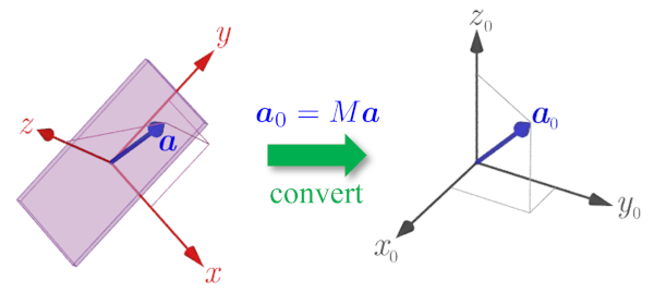
Conversion from device-fixed system to stationary system